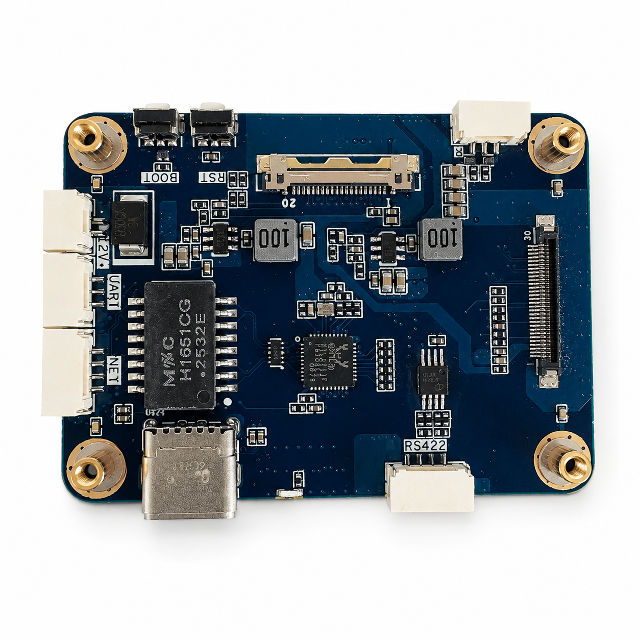
An AI video tracking board is only as valuable as the system it lands in. A capable board on its own is not a solution — camera selection, video input, latency, power, serial communication, and host integration all have to work together for the tracking output to be reliable. This guide walks through the four target integration scenarios, the hardware and software surfaces that matter at each, and the specific decisions that determine whether the board serves a production system or becomes shelf-ware in a lab.
1. AI Tracking Is Only as Good as Its Integration
The embedded AI vision industry has spent the past three years focused on inference performance — larger models, higher resolution, more classes, faster frame rates. That work has been necessary and valuable. But it has quietly overshadowed the fact that a production integration project succeeds or fails on a different set of variables: how the board fits into the physical airframe or chassis, how it accepts video from real-world cameras, how it talks to the host controller, how it survives the power and thermal environment, and how the operator or automation layer consumes its output.
An OEM team that specs a board on TOPS and detection accuracy alone will hit those integration walls at week four of the project. An OEM team that treats the board as one component in a system — and asks the integration questions before ordering — ships on schedule. This guide is written for the second kind of team.
The four sections that follow cover the four contexts this class of board most commonly integrates into: UAV, robotics, EO payload, and ground-station. Each has different constraints and each rewards different design choices.
2. What an AI Video Tracking Board Actually Is
The board is a compact embedded hardware module built around three components: a video ingest front-end, an NPU-accelerated processor running detection and tracking models, and an output stage that streams processed video and target-position data to a host system. Everything happens on the board. The host is never asked to run inference.
This is the key architectural distinction from software-only AI vision solutions that run inference on the host CPU or GPU. Software solutions have their place, but they leave the host with the inference workload — which competes with flight control, motion planning, or operator UI for compute and memory. A dedicated tracking board isolates the AI workload on purpose-built silicon and frees the host to do its primary job.
The processing pipeline on a well-designed board:
- Video ingest — one or two sensor channels via SDI, Cameralink, MIPI CSI-2, or USB
- Pre-processing — format conversion, scaling, color correction as needed
- AI inference — object detection producing bounding boxes with class labels and confidence scores
- Tracking — persistent target lock using selectable algorithms (centroid, correlation, multi-target, intelligent)
- OSD rendering — overlay of detection and tracking output on the video
- Encoding — H.264 or H.265 for network output
- Output — RTSP or UDP video stream over Ethernet, plus serial command/telemetry over UART or RS422
All seven stages run continuously and autonomously. The board only needs commands when the operator or host wants to change tracking algorithm, lock a new target, adjust OSD, or query status.
3. Four Target Integration Scenarios for an AI Video Tracking Board
The same hardware can serve very different systems. Understanding which scenario the integration targets shapes almost every other decision — power topology, cooling, cable lengths, output protocol, and firmware configuration all change.
Most OEM projects pick one primary scenario and configure the board for it. Platforms that need to serve multiple scenarios — a modular payload sold to both UAV and ground-station customers — should be built around a board that exposes the interfaces both scenarios need, rather than shipping two different SKUs.
4. Hardware Interfaces an AI Video Tracking Board Must Expose
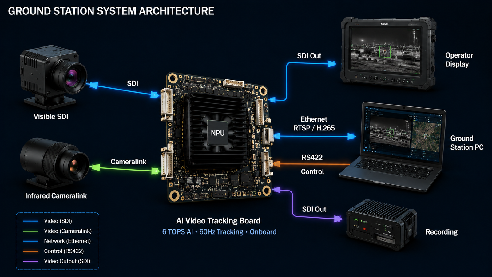
A production-ready board exposes six interface classes. Missing any one of them limits which host systems can integrate the board without external adapters.
| Interface | Purpose | Typical variant |
|---|---|---|
| Video input | Sensor data ingest | SDI (1080p), Cameralink Base, MIPI CSI-2 (2/4 lane), USB UVC |
| Video output | Processed video to host or display | Ethernet RTSP/UDP (H.264/H.265), SDI (1080p) |
| Serial control | Command and telemetry channel | UART (3.3V TTL), RS422 (differential, longer cable runs) |
| Power input | Board and payload power | 9-16 V DC (airframe-friendly), 12 V DC (industrial) |
| GPIO / auxiliary | Status LEDs, sync signals, triggers | 3.3 V logic level, configurable direction |
| Debug / service | Firmware update and low-level access | USB-C service port, BOOT and RST pushbuttons |
Two interfaces deserve specific attention because they are where integration problems most often surface.
Serial control choice — UART or RS422. UART is simpler and cheaper but limited to short cable runs (under 1 meter reliably). RS422 is differential and handles 15+ meters. In a UAV payload the board and host are inches apart, so UART is fine. In a ground-station or robotics platform where the board is 5-10 meters from the host controller, RS422 is required. Pick based on cable length, not preference. Teams new to the MIPI CSI-2 video input path can reference the official MIPI Alliance CSI-2 specification for signaling and lane configuration details.
Video output — network stream and SDI in parallel. Modern boards ship with both because different downstream systems consume different formats. The network stream feeds software platforms, recording systems, and modern ground stations. The SDI output feeds legacy FPV headsets, backup monitors, and any system that expects analog video. Running both in parallel is the professional-grade configuration.
5. Sensor Pairing — Visible, Thermal, and Customized Combinations
An AI video tracking board is only as useful as the sensor package it pairs with. The three common configurations:
Visible-only. Single SDI or MIPI input from a visible-light camera. Fits daytime inspection, sport tracking, industrial machine vision, and any application where lighting is controlled or ambient light is sufficient. Simpler integration, lower cost, familiar tuning.
Thermal-only. Single Cameralink or USB input from a thermal sensor. Fits perimeter monitoring at night, search and rescue, wildlife tracking, and detection tasks where thermal contrast is the strong signal. Requires thermal-adapted detection models — visible-light models trained on RGB imagery do not transfer directly to thermal.
Visible + thermal dual-channel. Both sensors feeding the board simultaneously. Enables cross-modal fusion — detection on the thermal channel triggers confirmation on the visible channel, or vice versa. The dual-channel configuration is where AI video tracking pulls ahead of single-sensor solutions the most, because most missions run into lighting conditions where one modality alone is insufficient.
Beyond the standard configurations, professional boards accept customized sensor combinations as part of the OEM integration. Depth sensors for robotics, event cameras for high-dynamic-range applications, hyperspectral for agriculture — the board handles the processing, and the sensor selection follows the mission. Confirm sensor compatibility with the board vendor before committing to a specific camera model.
6. Software Support That Separates Production Boards from Prototypes
Hardware is only half the integration story. The software support that ships with the board decides whether the OEM team can integrate in two weeks or spends two months reverse-engineering the protocol.
Four software components typically ship with a professional board:
- Serial protocol documentation. A complete reference for the command channel — command IDs, argument formats, response formats, error codes, checksum calculation. Without this, the OEM cannot talk to the board at all.
- Host-side sample code. Source code showing how to open the serial connection, send commands, parse responses, and handle common error conditions. Cuts weeks off integration for teams new to the board.
- Operator console application. A ready-built PC application that connects to the board and exposes all its features through a UI. Essential for development, testing, and demonstrating capability to end customers.
- Optional SDK or algorithm libraries. For teams that want to run custom detection models, integrate additional tracking algorithms, or extend the board's default behavior. Not required for standard integration but valuable for platforms with unique requirements.
A board that ships with all four is a production-ready product. A board that ships with only the protocol document is a hardware platform — usable, but requires significant software work by the integrator. Confirm which tier of software support comes with the module before quoting delivery dates to end customers.
7. Latency Budget Across the AI Video Tracking Board Pipeline
End-to-end latency — from photon at the sensor to target position at the host — is one of the most under-specified numbers in these integration projects. A typical well-designed pipeline runs 60-150 ms depending on configuration.
| Pipeline stage | Typical latency | Optimization lever |
|---|---|---|
| Sensor readout + format conversion | 10-30 ms | Choose sensors with global shutter or fast readout modes |
| AI inference | 20-50 ms | Model size, batch size, NPU utilization tuning |
| Tracking algorithm | 5-15 ms | Algorithm choice — centroid is fastest, intelligent is slowest |
| OSD rendering + encoding | 10-30 ms | Encoder settings, bitrate, I-frame interval |
| Network transport | 5-40 ms | Wired vs wireless link, jitter buffer settings |
Applications with tight closed-loop control requirements — a UAV auto-following a maneuvering target, a robotics gripper tracking a moving object — should specify a target latency at the start of the project and confirm the board can hit it in the intended configuration. Applications that only display tracking to a human operator are more forgiving; 150-200 ms is unnoticeable in most operator UIs.
The two levers with the most impact: choosing the right AI model for the compute budget (a lighter model that runs faster often beats a heavier model that produces marginally better detections) and running the board's encoder in low-latency mode with a short I-frame interval.
8. Power and Thermal Design
A board that runs perfectly on a bench power supply can still fail in a real integration if the power and thermal design of the enclosure is under-specified. Two failure modes recur.
Power brownout under load. AI inference draws bursty peak current — a board rated at 5 W average may pull 12 W for short bursts during heavy detection scenes. If the supply cannot deliver the peak, the board browns out and either resets or enters an undefined state. Solutions: size the supply for peak current not average, add local bulk capacitance near the board's power input, and confirm the aircraft or vehicle bus can handle the load without sagging.
Thermal throttling. Every NPU has a maximum sustained temperature above which it throttles clock rate — which reduces inference throughput and increases latency, sometimes dramatically. In a small enclosure with limited airflow (typical for a gimbal or a compact UAV payload), thermal throttling can start within minutes of sustained load. Solutions: thermal simulation of the enclosure at design time, thermal pad or heat spreader on the NPU, and forced airflow if the mechanical design allows.
Both failure modes are prevented by treating the board as a system component with a defined power and thermal specification, not as a magic module that just works. The datasheet numbers for input voltage and operating temperature are the starting point of the design, not the answer.
9. Testing and Validation Before Production
Every board integration project should include four testing stages before committing to production volume. Skipping any of them adds risk that only surfaces after units are in the field.
- Bench integration. Board on the desk, camera on a tripod, host on a laptop. Confirm every interface works, commands respond, video streams. This is a one-day exercise if the software support is good.
- System integration. Board installed in the actual enclosure or airframe, wired to actual host, powered by actual bus. Confirm no interference, no thermal issues, no cable-length surprises. Typically a week of iteration.
- Field trial. System operated in the deployment environment against real targets. Confirm detection accuracy, tracking robustness, and operator workflow. Multi-week exercise with feedback loop back to configuration.
- Endurance test. System operated continuously for 24-72 hours in the target thermal and vibration environment. Confirms nothing drifts, no memory leaks, no thermal throttling under sustained load.
OEMs that run all four stages before ordering production volume ship platforms that work. OEMs that skip stages three or four in the interest of speed usually discover integration issues after the first customer deployment — where the cost of fixing them is 10-100x what it would have been in the lab.
10. Ten Common AI Video Tracking Board Integration Mistakes
- Under-sized power supply. Rated for average current, fails on peak. Size for peak, add bulk capacitance.
- Wrong serial protocol choice. UART where RS422 is needed for cable length. Match to the deployment, not the prototype.
- Sensor format mismatch. Camera outputs 4K, board expects 1080p. Confirm format compatibility before ordering samples.
- Thermal enclosure under-designed. Board throttles after 10 minutes. Simulate thermal at design, not after.
- No plan for firmware updates. Fleet deployed, first bug fix requires shipping units back. Design an OTA path from day one.
- Skipping the sample phase. Ordering production volume before bench testing the actual configuration. Order 1-2 samples first, always.
- Wrong AI model for the compute budget. Heavy model, low frame rate, missed targets. Match model to NPU capability.
- Not testing the operator UI. Board works, operator can't figure out how to lock a target. Include operator workflow in field trials.
- Ignoring latency until integration. System works but too slow for closed-loop control. Specify latency budget upfront.
- Missing software support tier. Board ships with only a protocol PDF, no sample code. Confirm software deliverables before ordering.
11. Frequently Asked Questions
An AI video tracking board is a compact embedded hardware module that accepts one or more live video inputs, runs AI-based detection and object tracking on the video in real time using an onboard NPU-accelerated processor, and outputs both the processed video stream and target-position data over standard interfaces. It sits between the camera and the host system — a UAV flight controller, a robotics main controller, an EO gimbal, or a ground-station PC — and offloads all inference work from the host so the host stays free for its primary control tasks.
A production-ready AI video tracking board typically exposes six interface classes: (1) video input — SDI, Cameralink, MIPI CSI-2, or USB depending on the sensor; (2) video output — Ethernet RTSP/UDP for network streaming and often SDI for direct display; (3) serial control — UART or RS422 for command and telemetry; (4) power input — commonly 9-16 V DC to match airframe or vehicle bus voltage; (5) auxiliary GPIO for status LEDs and trigger lines; (6) debug ports — BOOT/RST buttons and a service USB for firmware updates. Which specific interfaces matter depends on the target host system.
In a UAV integration the board sits between the camera payload and the flight controller. Video comes in from the camera (visible, thermal, or both). AI inference and tracking run on the board. The board outputs a compressed video stream over Ethernet or the aircraft's downlink, plus target-position error (miss distance) over a serial channel to the flight controller. The flight controller uses the miss-distance data to command gimbal servos or fly the aircraft to keep the target centered. The host is never asked to run inference.
Yes. Professional boards support both visible and thermal camera inputs, either individually or in dual-channel configurations. Visible cameras typically connect via SDI or MIPI CSI-2, thermal cameras via Cameralink, USB UVC, or MIPI depending on the module. The board processes each channel with a suitable AI model — visible-light detection models on visible input, thermal-adapted models on thermal input — and can fuse the two channels for cross-modal tracking on platforms that need both.
Four software components typically ship with a professional board: (1) a documented serial protocol for command and telemetry so the host can talk to the board; (2) host-side sample application source code showing how to send commands and parse responses; (3) an operator console application for testing and configuration during development; (4) optional SDK or algorithm libraries for teams that want to run custom models or extend the board's default behavior. The four together are what separate a production-ready board from a prototype platform.
End-to-end latency from photon at the sensor to target position at the host typically runs 60-150 ms on a well-designed pipeline. Contributors: sensor readout and format conversion (10-30 ms), AI inference (20-50 ms depending on model), encoding for network output (10-30 ms), transport (5-40 ms depending on link). Applications that require tighter latency — high-speed target following, precision manipulation — should specify a latency budget upfront and confirm the board can hit it in the target configuration before committing.
Six recur across projects: (1) under-specified power supply causing brownout resets under load; (2) wrong host interface protocol assumption (using UART when RS422 is required for cable length); (3) sensor input format mismatch (camera outputs 4K, board expects 1080p); (4) inadequate thermal design in the enclosure causing sustained NPU throttling; (5) no plan for firmware updates once units are deployed; (6) skipping the sample-and-test phase and going straight to production quantity. Each is preventable with a pre-order technical review.
12. Conclusion: The Board Is a Component, Not a Solution
An AI video tracking board gives an OEM system integrator the AI vision capability their platform needs, without requiring the OEM team to become an AI research group. That is the value proposition, and it is a strong one. But it only lands when the integration around the board is treated with the same rigor as the board itself.
The pattern that works: pick the target scenario first, confirm the interfaces match the host system, specify the sensor package, plan the power and thermal envelope, and confirm the software support tier before ordering. Order samples for bench testing. Move to system testing in the actual enclosure. Field-trial with real targets. Endurance-test before production. Every step catches issues that would otherwise land in the field, where fixing them costs 10-100x what the lab fix would have cost.
AERVUE Technology supplies AI video tracking boards under the TracVue product line to OEM system integrators worldwide, with hardware configurations spanning visible-only, thermal-only, and dual-channel setups. Our engineering team provides the interface documentation, serial protocol reference, host sample code, operator console application, and integration support that turn a hardware platform into a shipping product. If your team is developing an intelligent tracking or autonomous vision system, we would rather work through the integration questions before you order than after.
For adjacent topics, our companion guides on AI video tracking ground stations, thermal camera integration for drones, and AI vision for BVLOS drones cover the wider decision framework that surrounds this class of integration.
Developing an intelligent tracking or autonomous vision system?
Send us your platform and integration scenario, and we will match a TracVue board configuration to your requirements, walk through interfaces and software support, and ship an evaluation sample within 1-3 days. Factory-direct pricing from sample to volume.