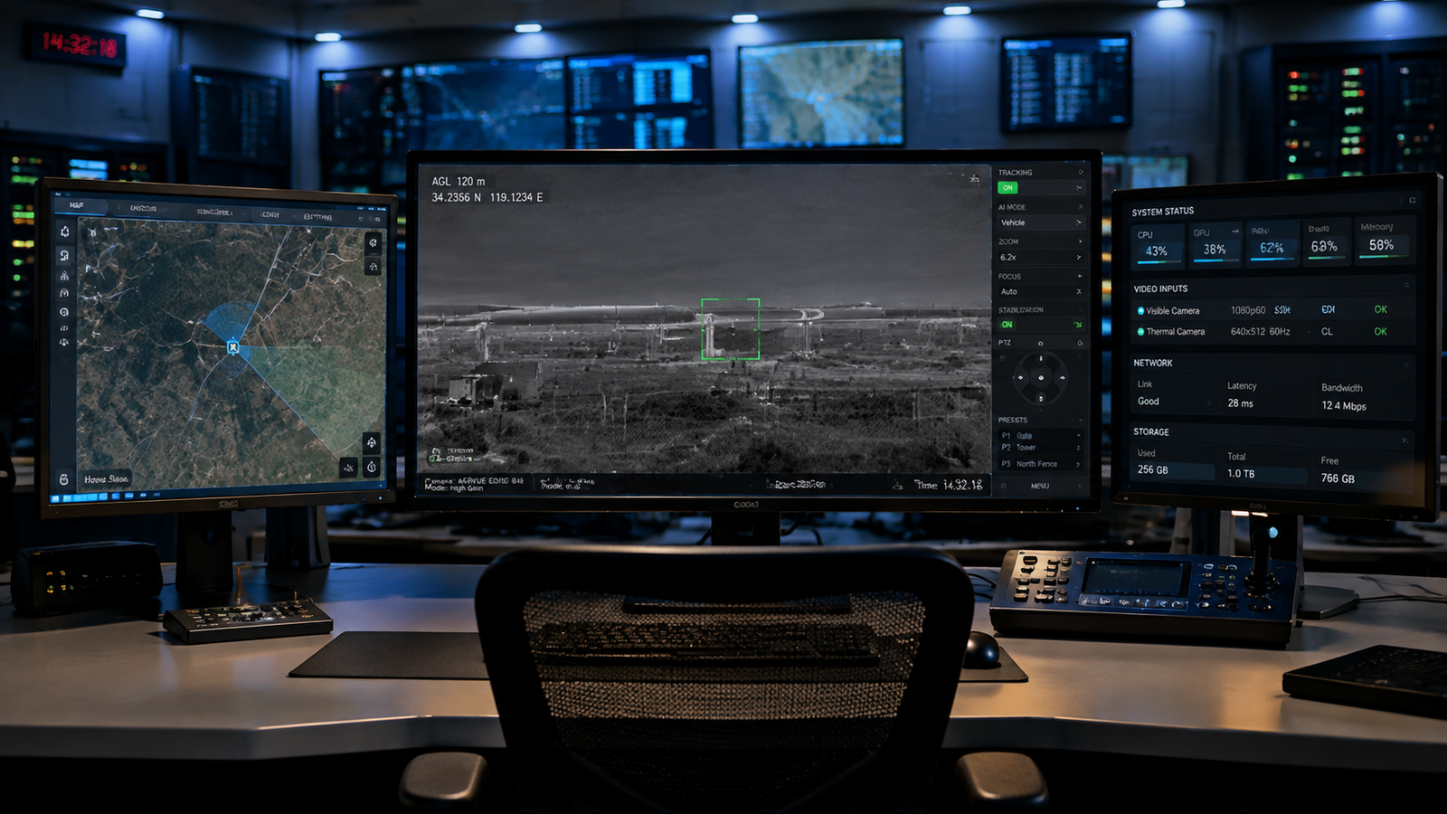
An AI video tracking ground station is where the AI's detection and tracking output becomes actionable for the operator. Choosing the right tracking board is only the first step. The integration work that connects the board to the operator — network, video pipeline, serial control, tracking algorithms, on-screen display, firmware updates — is what decides whether the deployment works in the field or stalls at commissioning. This guide walks through the architecture layers, the setup workflow, the four tracking algorithm families, and the mistakes that cost OEM integration teams the most time.
Introduction: Why the Ground Station Is Where AI Video Tracking Pays Off
An AI video tracking board is a small piece of hardware — typically a compact PCB with a dedicated NPU-accelerated SoC, video input ports, network output, and a serial control channel. On its own it does nothing visible. The value shows up when the board is wired into a complete system: cameras feed video in, the AI runs onboard detection and tracking, and the results reach an operator who can see what the aircraft or turret is looking at, lock a target, and issue control commands.
That last part — from the tracking board to the operator — is the AI video tracking ground station. It is more than just a monitor and a laptop. It is a small but complete system with its own architecture: a network layer that carries video and control, a serial layer that handles low-level parameter control, an operator display that visualizes the tracking state, and a software layer that translates operator intent into commands the board understands.
Most integration projects that stall at commissioning stall at the ground station, not at the tracking board. This guide covers what a professional ground station looks like, how to build one, and the specific decisions that decide whether the field deployment works.
1. What an AI Video Tracking Board Actually Does
Before the ground station, it helps to be clear about what the board is producing. A modern professional-grade AI video tracking board delivers four categories of output:
AI-based detection. The board runs an onboard AI model that continuously scans the incoming video for specific target classes. Typical trained classes on civil-grade boards include people, vehicles, boats, and aircraft (including small UAVs). Detection returns the target class, position (bounding box coordinates), and size.
Continuous tracking. Once a target is locked — automatically by the AI, or manually by the operator via a point or box selection — the board maintains tracking across frames, outputting miss-distance data (target position relative to the video center) that a servo control loop can consume to keep the target centered.
Video output. The board re-encodes the input video (with tracking overlays) and outputs it in two forms: a network video stream (H.264 or H.265 over RTSP or UDP) for the operator PC, and an SDI output for a local monitor.
Command and telemetry. The board accepts commands over a serial channel (typically RS422) — track this target, switch input channel, change palette, digital zoom to 4x, save a snapshot — and returns telemetry back on the same channel.
Everything in the ground station is designed around consuming these four outputs and issuing commands back to the board. Once the four outputs are clear, the ground station design falls out naturally.
2. AI Video Tracking Ground Station Architecture — Four Layers
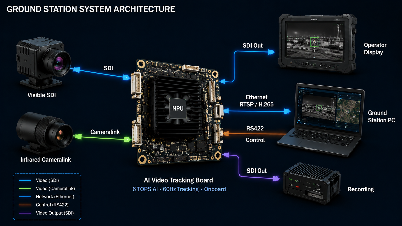
An AI video tracking ground station has four functional layers, each of which needs to be planned separately during OEM integration.
| Layer | What it carries | Physical medium | Typical destination |
|---|---|---|---|
| Video stream | H.264/H.265 encoded live video with OSD overlays | Ethernet (RTSP or UDP) | Operator PC + optional wall display |
| Local display | Uncompressed SDI video with OSD overlays | SDI (BNC or MCX-to-BNC) | Dedicated operator monitor |
| Control channel | Commands to board, telemetry back to operator | RS422 (via USB-to-RS422 adapter) | Operator PC serial port |
| Configuration and firmware | Web-based board configuration and firmware upload | Ethernet (HTTP on port 8080) | Operator PC web browser |
The two Ethernet-based layers (video stream + configuration) share the same physical cable. The SDI output is a separate optional path for a dedicated monitor. The RS422 channel is a separate physical connection that carries the low-latency command stream. Understanding this four-layer split is the first step to a clean integration.
3. Network Layer Setup
The network layer is the first thing to configure. A typical professional tracking board ships with a default IP address such as 172.16.0.240 on a 255.255.255.0 subnet. The operator PC must be set to an address in the same subnet — say 172.16.0.10 — with the same subnet mask.
The steps are the same across operating systems, only the menu paths differ. On Windows: Control Panel > Network and Internet > Network and Sharing Center > Change adapter settings, then right-click the Ethernet connection, open Properties, and double-click IPv4 to set the address. On macOS: System Preferences > Network > Ethernet > Advanced > TCP/IP. On Linux: ifconfig or the newer ip command from the terminal.
After setting the IP, a simple ping 172.16.0.240 from a terminal or command prompt confirms the network is up. If ping fails, the culprit is almost always the Ethernet cable, the connector, or an incorrect subnet on the PC — not the tracking board. Ruling out the cable first saves debugging time.
Once ping succeeds, the RTSP video stream becomes accessible at a standard URL such as rtsp://172.16.0.240:8554/live/stream. Any RTSP-compatible player — VLC, ffplay, GStreamer, or a purpose-built operator console — can display the live feed. The board's configuration page becomes accessible on the browser at http://172.16.0.240:8080 for firmware upgrades and parameter changes. For teams implementing custom RTSP clients or debugging protocol-level issues, the IETF RTSP 2.0 specification (RFC 7826) is the authoritative reference.
4. Video Pipeline — Handling Dual-Sensor Inputs
Professional-grade AI video tracking boards accept two video inputs simultaneously — typically one SDI channel and one Cameralink Base channel. The SDI channel usually carries the visible-light feed at 1080p or 720p, with adaptive frame rate support at 25, 30, 50, or 60 Hz. The Cameralink Base channel typically carries the infrared feed, with the pinout defined per the standard Cameralink SDR-26 connector layout.
The board can switch the active processing channel on command, so the operator can toggle between visible and infrared views from the ground station without touching the hardware. Some boards also support picture-in-picture display, where the non-active channel appears as a small overlay window in a corner of the main output.
The output side of the video pipeline is symmetric: one compressed network video stream (H.264 default, H.265 configurable) and one uncompressed SDI output at 1080p 30 Hz. The RTSP output supports configurable bitrate and I-frame interval, which matters for tuning bandwidth against video quality on constrained network links.
A word on the SDI output — most professional boards use an MCX connector on the PCB for board-space reasons, with an MCX-to-BNC coax adapter cable shipping with the unit. Standard BNC-terminated cables plug into the adapter and then run to the operator monitor.
5. Control Layer — RS422 Command Channel
The RS422 serial channel is what makes the ground station interactive. Every command that changes the board's behavior — track this target, switch input, zoom in, change palette, save snapshot — travels over this serial link. It runs in parallel with the Ethernet channel because serial control gives lower and more predictable latency than routing commands through a network stack, and it works even if the network is momentarily degraded.
Physical integration is straightforward. A DB9 female connector on the ground station side connects to a USB-to-RS422 adapter, which plugs into the operator PC's USB port. The PC sees the adapter as a standard serial port (COM3 or /dev/ttyUSB0 depending on OS), and any serial terminal or the vendor's operator software can open the port to send commands.
Wiring the RS422 pairs correctly is one of the top sources of "no serial response" surprises in a new AI video tracking ground station deployment. RS422 uses differential pairs — TX+ and TX− going one way, RX+ and RX− the other way — and reversing a pair or swapping TX and RX yields no communication. The board's datasheet defines the exact pinout on its main interface connector (typically a J30J-21ZKW-J or equivalent), and following the pin table is mandatory. Wiring by intuition rarely works on the first try.
Beyond board control, the RS422 channel also carries pass-through commands to peripheral hardware — a camera control head, a pan-tilt servo controller, a fast-steering mirror. This lets the ground station issue commands through a single serial channel to the entire optical payload, rather than running a separate serial run for each device.
6. AI Tracking Algorithms Explained
The tracking algorithm is the heart of what the board does — and professional boards typically offer four algorithm families, each suited to different mission profiles. A good operator console lets the user switch between them on demand as the mission unfolds.
Centroid tracking. Best for small, weak-signal targets against a low-clutter background — long-range UAV detection is the canonical use case. The algorithm computes the intensity centroid of the target region and follows it across frames. Robust when the target is far enough away that no fine features are resolvable, but only its "hot spot" or contrast against background is trackable.
Correlation-filter tracking. The operator selects a region of the image, the board builds a template from that region, and subsequent frames are searched for the best match. Works for arbitrary user-selected targets — vehicles, buildings, animals, any distinguishable region — and is not tied to specific AI-trained classes. The workhorse tracking mode for general use.
Multi-target tracking. Assigns persistent IDs to multiple detected objects in the scene, which reduces the frame-to-frame identity switching problem when several similar targets are present. The operator can then lock a specific ID rather than losing track when two vehicles cross paths. Also useful for building an event log of everything the system saw during a mission.
Intelligent tracking. Combines AI classification with correlation-filter tracking. The AI confirms that the tracked object still matches its trained class (person, vehicle, boat, aircraft) and the correlation filter maintains position, with cross-validation between the two. This solves the failure modes that pure correlation-filter tracking has with target deformation, rotation, rapid motion, and rapid zoom changes.
The lock modes complement the algorithms. Manual point selection, manual box selection, image center lock, crosshair lock, and target-ID lock (in multi-target mode) all correspond to different operator workflows. Auto-search mode uses the AI to detect targets of a specified class across the field of view and enter tracking automatically when one appears — useful for unattended monitoring where the operator does not need to be at the console every second.
7. OSD and Operator Display Design
The on-screen display (OSD) overlays operator-critical data directly onto the output video stream. The overlay comes out of the board itself, so both the SDI monitor and the RTSP stream carry the same OSD — the operator sees the same information regardless of which display path is used. A well-designed OSD gives the operator situational awareness in a single glance without cluttering the video.
Typical OSD elements on a professional tracking board:
- Top-left cluster — timestamp, input frame rate, active tracking channel, detection state, digital zoom level
- Bottom-left rolling status — core temperature, IP address, firmware version (rotating so each fits in a small area)
- Center overlay — tracking gate (target bounding box), crosshair, cursor, tracking state info (gate position and size)
- Top and left edges — miss-distance indicators showing the target's horizontal and vertical offset from the video center as real-time angle values
- Picture-in-picture (when active) — the non-primary channel as a small window in the bottom-right corner
Every element should be individually toggleable and color-configurable through the operator software. A daytime mission with a bright sky needs a different OSD color scheme than a night mission on a dark scene. Locking the display style to one preset limits what the deployment can do.
Digital zoom is worth flagging separately. Professional boards typically support up to 16x digital zoom with 0.1x precision. Digital zoom does not add resolution — it just crops and scales — but it lets the operator visually confirm a tracked target's identity without touching the optical zoom on the camera itself. For manned-monitoring workflows this is a valuable operator affordance.
8. Fault Codes and Self-Check
A professional tracking board runs a continuous self-check and exposes any faults through a bit-defined fault register that the operator software can read over the serial channel. Each bit represents a specific failure category. When the operator sees an unusual system behavior, reading the fault register is the first diagnostic step.
Typical fault categories on a professional board:
| Bit | Fault | Likely cause |
|---|---|---|
| 0-1 | Video input fault (channel 0 or 1) | Loose connector, interference, unsupported format |
| 2-3 | Video processing fault | Firmware crash on that channel |
| 4-5 | NPU fault (channel 0 or 1) | Undervoltage, SoC damage |
| 6-8 | Tracking algorithm fault | Algorithm-specific failure |
| 9-10 | OSD fault | Rendering pipeline failure |
| 11 | H.264/H.265 encoder fault | Encoder hardware issue |
| 12 | RTSP server fault | Network path unavailable |
| 13-14 | Video recording or snapshot fault | Storage full or corrupted |
| 15 | SDI output fault | SDI encoder hardware damaged |
The fault register is not a substitute for good integration testing — but it makes field diagnostics much faster than opening a housing to inspect. An operator console that surfaces the fault bits as human-readable messages saves a support call.
9. Firmware Updates and Long-Term Maintenance
Firmware updates on a professional tracking board are typically delivered through a browser-based upgrade page hosted on the board itself. The workflow is straightforward:
- Confirm the board is powered and networked, with the operator PC on the same subnet
- Open a browser to the board's upgrade URL — typically
http://172.16.0.240:8080 - Drag the firmware package (a .swu file or equivalent) into the upgrade page's drop zone, or click to browse
- Confirm the upgrade and wait — the display goes black for about 15 seconds during reboot
- Verify the new firmware version against the version number in the board's OSD
The browser-based upgrade path removes the need for special update tools, which matters at scale. A fleet of 50 ground stations can be updated remotely by any operator with a laptop and network access, without needing to ship each board back to the factory.
For maintenance record-keeping, most professional boards also expose a runtime log queryable over the serial or network channel. The log captures fault events, firmware changes, and calibration events with timestamps. Reading and archiving this log periodically is what makes a fleet auditable across its service life.
For a wider view of firmware and maintenance considerations that apply to any OEM sensor integration — thermal, visible, or AI — our companion guide on thermal camera integration for drones covers the parallel considerations that show up on the payload side of the same system.
10. Common Mistakes to Avoid
Ten years of watching OEM integration projects hit the same rocks yields a short list of mistakes worth flagging upfront. Every one of these costs an integration team hours to days when it happens in the field.
Mismatched network subnets. The board defaults to 172.16.0.240 and the operator PC is set to a 192.168.x.x address on the corporate LAN. Ping fails, the team spends an hour debugging, and the fix is a two-minute IP setting change. Confirm subnet match before any network-level debugging.
Reversed RS422 wiring. Swap the TX+ and TX− pair, or wire the TX from the board to the TX on the PC instead of RX, and serial communication silently fails. There is no error message — the port simply returns no data. Verify pin-by-pin against the board's datasheet.
Color bar output interpreted as no signal. When the board has no valid input on a video channel it outputs a color-bar pattern as a "no input" indicator. Some integration teams see the color bar and assume the board is broken, when the actual issue is a wrong resolution or frame rate on the camera side. Most professional boards do not auto-adapt to arbitrary input formats — they need the format they were configured for.
Unstable 12 V DC power. A power supply that sags under load, or noise on the DC line from other equipment, can cause the board to reset intermittently. On a mast-mounted deployment this is a service call. A conditioned DC feed with proper regulation and sequencing avoids this class of failure.
Assuming SDI output failure means board failure. If the SDI monitor shows nothing but the RTSP stream is fine, the fault is in the SDI encoder chip or the coax connection, not the board's core function. The fault register (bit 15) confirms which side is broken.
Skipping the self-check routine. A structured 10-minute self-check at commissioning — ping test, RTSP stream test, SDI monitor test, RS422 command loopback, fault register read — catches all of the above before the platform is fielded. Skipping this to save time in commissioning almost always costs more time in the field.
Frequently Asked Questions
An AI video tracking ground station is the operator-side system that receives video streams and tracking data from an AI-enabled video tracking board — usually deployed on a drone payload, mast-mounted turret, or fixed camera. It combines a real-time video display, a network control interface for issuing commands, a serial command channel for low-level parameter control, and operator software that visualizes the tracking state. The ground station is where the AI's detection and tracking output becomes actionable for the operator.
A professional-grade AI video tracking board typically exposes four interface classes: video input (SDI for visible light, Cameralink Base for infrared or industrial sensors), video output (network RTSP stream and SDI to a local display), control (RS422 serial for command and telemetry), and network (1000BASE-T Ethernet for streaming, configuration, and firmware updates). Ground station integration involves wiring these four channels to the right destinations.
Four algorithm families dominate professional video tracking boards. Centroid tracking works best for small, weak-signal targets against a low-clutter background — long-range UAV detection is the classic use case. Correlation-filter tracking creates a template from a selected image region and follows it across frames, useful for arbitrary user-selected targets. Multi-target tracking assigns persistent IDs to multiple objects in the scene to reduce false detections and identity switching. Intelligent tracking combines AI classification with correlation-filter tracking to handle target deformation, rotation, rapid motion, and zoom changes.
Three physical connections are typical. Ethernet carries the RTSP video stream and the network control protocol between the tracking board and the ground station PC. A USB-to-RS422 adapter connects the ground station PC to the board's serial command interface for low-level control. An SDI cable optionally goes from the board's video output to a dedicated operator display monitor. The ground station PC's IP address must be set to the same subnet as the tracking board — a common default is 172.16.0.x with the board at 172.16.0.240.
The OSD (on-screen display) overlays operator-critical data directly onto the output video stream. Typical elements include timestamp, input frame rate, active tracking channel, detection state, digital zoom level, target bounding box, crosshair, ruler, north indicator, GPS coordinates, and yaw/pitch angle indicators for miss-distance to the target. Most professional boards allow the operator to enable, disable, and recolor individual OSD elements to match the deployment's mission and lighting conditions.
Firmware updates are typically delivered through a browser-based upgrade page hosted on the tracking board itself. The operator connects to the board over Ethernet, opens a browser to the board's IP address on the upgrade port (commonly port 8080), and uploads the firmware package. The board applies the update, reboots, and comes back online within about 15 seconds. The operator then verifies the new version number against the OSD version display to confirm success.
Five mistakes account for most delays. First, mismatched network subnets between the board and the operator PC. Second, wiring the RS422 with reversed pairs and getting no serial response. Third, connecting a camera with a resolution or frame rate the board does not support and interpreting the resulting color-bar output as no signal. Fourth, unstable 12 V DC power to the board causing intermittent restarts mid-mission. Fifth, assuming SDI output failure means board failure when the actual issue is the SDI encoder chip or output cable. A structured self-check routine catches all five in about 10 minutes.
Conclusion: The Ground Station Is the Multiplier
A great tracking board with a poor AI video tracking ground station underdelivers. A modest tracking board with a well-integrated ground station overdelivers. The four-layer architecture — video stream, local display, control channel, configuration path — is not complicated once it is written down, but each layer has its own decisions that compound into a smooth or painful deployment.
The pattern that works: plan the four layers before wiring anything, confirm subnet and cable basics before writing any software, pick the tracking algorithm to match the mission profile rather than the datasheet marketing, and build the operator console around the fault register from day one. Do those four things well, and the ground station becomes the multiplier that turns a good AI tracking board into a deployable system.
AERVUE Technology supplies AI video tracking boards under our TracVue product line, along with the ground station integration support that OEM integrators need to turn a sample board into a fielded deployment. Whether you are scoping a drone-payload integration, a mast-mounted perimeter surveillance system, or a fixed-installation optical monitoring platform, our engineering team can walk through the ground station architecture against your specific mission, recommend a configuration, and ship a sample within 1 to 3 days.
For adjacent integration topics on the payload side, our companion guides on thermal camera integration for drones, AI vision for BVLOS drones, and the infrared camera for drones market cover the decisions that sit on the other side of the same system.
Scoping an AI video tracking ground station?
Tell us your platform (drone payload, mast turret, fixed installation), your mission profile, and your expected operating range. We will match a TracVue configuration, walk through the ground station architecture, and ship a sample within 1-3 days — with factory-direct pricing from sample to volume.