The hardest part of adding thermal to a drone isn't the camera itself. It's the thermal camera integration drone work that surrounds it. After enough OEM projects, the same ten questions come up every single time — and they're almost never in the spec sheet. This guide walks through the ten questions that decide whether a thermal payload project lands on time and on spec, or stalls out at week six with the engineering team blocked on something no one asked about upfront.
Introduction: Why Thermal Camera Integration Is the Hard Part
Selecting a thermal sensor is the easy part of building a thermal-equipped drone. Resolution, NETD, radiometric accuracy, weight — these are on the datasheet, they're comparable across vendors, and a good product manager can pick the right module in a spreadsheet. The hard part is what happens after the module ships and the integration team has to make it work inside a real airframe with a real flight controller, a real ground station, and a real customer schedule.
Every experienced OEM knows the pattern. A thermal camera integration project that looked simple in the datasheet phase turns into a six-week debugging exercise once the team hits the interface, driver, or toolchain reality. The delay is rarely a component failure. It is almost always an unasked question from before the order was placed.
The ten questions below are the ones we see in every project. Each one, caught early, saves an OEM team a week or more. Caught late, each is a stalled project and a frustrated engineer. If you are speccing a thermal payload right now, work through this list before you commit.
1. Thermal Camera Integration Drone Wiring: MIPI or UART — And For What?
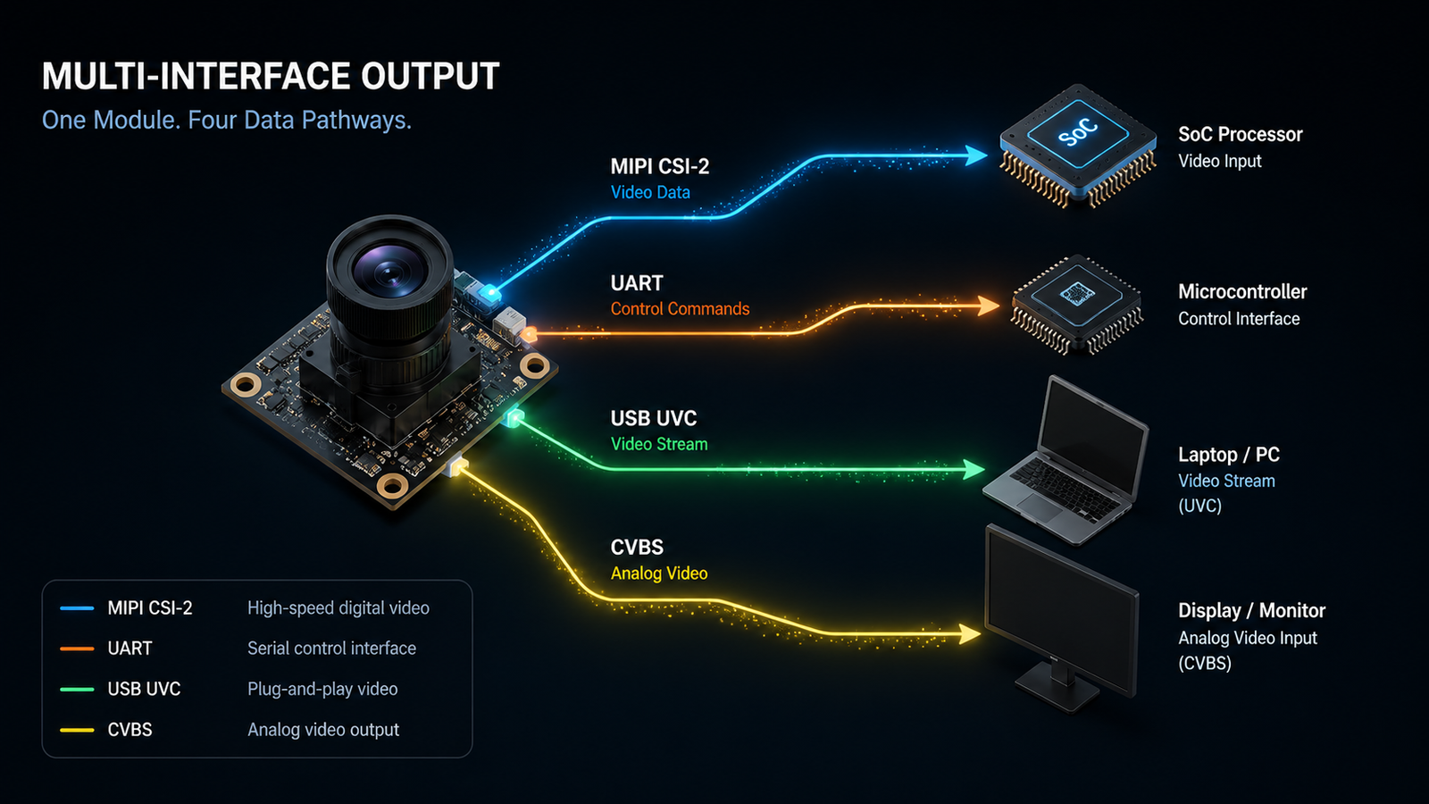
The first surprise on almost every thermal camera integration project is that video data and control commands travel on different buses. On most modules, high-speed video streams out over MIPI CSI-2 to the host SoC. Control commands — image settings, palette selection, gain switching, NUC (non-uniformity correction) triggers — travel over a separate UART bus to a microcontroller. Two interfaces, two jobs.
Teams that assume "one pipe does both" wire only one, then discover mid-integration that they cannot change palette, switch gain modes, or trigger NUC from software. The fix requires adding a second physical connection, updating the harness, and revisiting firmware. If the airframe is already assembled, this can cost days per aircraft.
The right upfront question: which bus carries video, which bus carries control, what signaling level does each expect, and can we wire both from day one? Most professional modules default to MIPI CSI-2 for video (2-lane or 4-lane depending on resolution and frame rate) and 3.3 V TTL UART for control. Confirm this against your specific module and log it in the integration plan before the first solder joint.
2. Do You Actually Need an SDK?
Vendor conversations about thermal integration often default to "we'll send you the SDK." Sometimes that's right. Often it's overhead the project doesn't need.
If the integration reads raw video over MIPI CSI-2 directly from the sensor, an SDK is often unnecessary. The MIPI protocol is documented, the sensor's register map is documented, and the integration team communicates with the sensor directly through the platform's V4L2 stack on Linux or the equivalent camera driver framework on the target OS. Adding an SDK layer here adds surface area without adding capability.
An SDK becomes necessary in three cases:
- USB UVC integration where the module presents itself as a UVC camera and radiometric data comes through a Y16 mode or vendor-specific extension unit
- Radiometric thermometry where per-pixel temperature values must be extracted, calibrated, and processed — a math and calibration table that vendors package into libraries rather than expose as raw
- Advanced processing features like image stabilization, palette rendering, or automatic gain control that the vendor implements in the SDK rather than in silicon
Ask which data path applies to the intended use case before requesting a library that may never be linked. If the answer is "raw MIPI video for observation," an SDK is optional. If the answer is "USB radiometric for inspection reporting," an SDK is required.
3. Which SoC Platform Is Your Camera Built On?
Compatibility between a thermal module and a host SoC is not about generic ARM support. It is about specific driver binaries, kernel modules, and toolchain builds for the exact silicon in use. A supplier who asks which SoC you are running before shipping is a supplier who has integrated before. One who does not will hand you a generic package and disappear when it does not compile.
Common host platforms for drone thermal camera integration in 2026 include:
| SoC family | Common use | Integration notes |
|---|---|---|
| Rockchip RK3566 / RK3588 | Cost-effective Linux platforms, growing AI focus | Mature V4L2 support, MIPI CSI-2 native |
| Ambarella CV22 / CV5 | Prosumer and enterprise camera-first designs | Vendor SDK-driven, tighter integration path |
| Qualcomm QCS-series | Higher-end professional platforms | Requires vendor NDA for full toolchain |
| NXP i.MX8 | Industrial and commercial UAV integrators | Yocto-friendly, good long-term support |
| Xilinx Zynq (AMD) | Custom high-performance edge processing | FPGA fabric enables custom sensor interfaces |
Ask for confirmation of driver support for the exact SoC, not just for the CPU family. "ARM Cortex-A55 supported" is not the same as "RK3566 driver package delivered and tested." The gap between those two statements is the gap between a smooth thermal camera integration drone project and a stalled one. For teams unfamiliar with the MIPI CSI-2 spec that most modules use for video output, the official MIPI Alliance CSI-2 documentation is the authoritative reference for signaling and lane configuration.
4. Observation vs Thermometry — Different Integrations
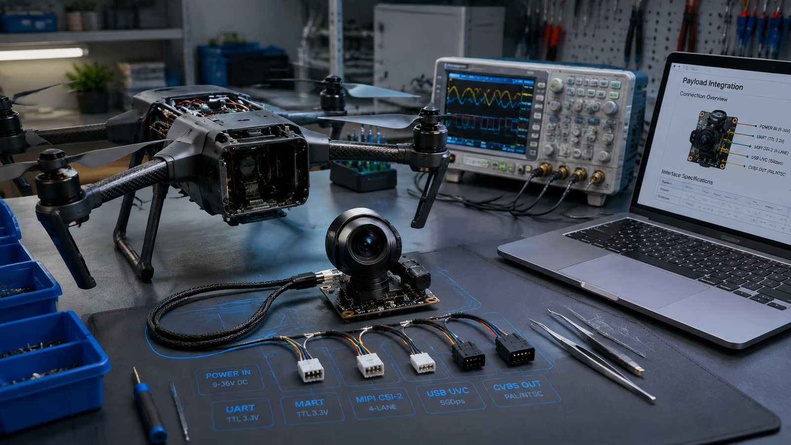
The most consequential architectural decision in thermal camera integration drone projects is choosing between observation and thermometry paths. These are not just different features. They use different data paths and different control methods, and picking the wrong one means redoing the integration.
Observation modules output video only — visualized thermal patterns rendered through a color palette for situational awareness. Typical integration: MIPI CSI-2 video to SoC, minimal software, direct display or recording. Fine for search and rescue, general awareness, firefighting overview.
Thermometry (radiometric) modules output per-pixel temperature values with defined accuracy — typically ±2°C industrial-grade or ±0.5°C higher-tier. Integration is different: USB UVC Y16 raw mode or vendor-specific extension unit, temperature calibration table processing, and SDK-based parsing to produce usable temperature values from the raw sensor data. Required for asset inspection, electrical fault detection, energy audits, and any workflow that generates temperature-based reports.
Teams that build for observation and then get asked to add radiometric mid-project often discover the module they chose does not expose the Y16 data at all, or exposes it through a path their platform does not support. The fix is a hardware change. The right question at the start is: does the mission ever need to answer "how hot?" rather than just "where is the hot part?"
5. Toolchain Match Matters More Than "Linux Support"
Vendor documentation that says "Linux support" is nearly meaningless without more detail. Linux is not one target. It is dozens of architecture, kernel, glibc, and compiler combinations, most of which are not mutually compatible at the binary level. This is one of the most costly hidden traps in thermal camera integration drone projects because it looks like a solved problem until the build breaks.
The specifics that matter:
- Architecture — is the shared library or driver built for ARM v7, aarch64 (ARM64), x86_64, or RISC-V? A .so compiled against the wrong architecture will not link.
- Compiler and version — GCC 9, 10, 11, 12? Clang? A driver built against GCC 9.4 may fail to link into a project built with GCC 11.2 depending on ABI dependencies.
- Kernel version and interface — is the driver a kernel module for a specific kernel version, or a user-space library that works across versions?
- glibc version — musl-based systems (Alpine, some embedded builds) will not link against glibc binaries and vice versa.
- Linaro or vendor toolchain — Linaro releases, vendor-provided toolchains, and mainline GCC all produce slightly different binaries.
Before ordering, confirm the target architecture, compiler and version, glibc version, and toolchain source. A one-week debugging cycle from mismatched toolchains is one of the most common causes of project slippage — and one of the easiest to prevent by asking upfront.
6. Thermal Camera Integration Drone Frame Sync and Latency Budget
Modern thermal camera integration drone projects rarely stop at a single sensor. Thermal is paired with visible, sometimes with a third sensor, and increasingly with an onboard AI inference module that fuses their outputs. This is where frame synchronization becomes central.
Two sensors rarely run at the same frame rate or start their frames at the same instant. Thermal typically runs at 25 or 30 Hz. Visible often runs at 30 or 60 Hz. If the integration wants to overlay them, run cross-modal detection, or geo-register both streams to the same aircraft pose, the frames need a common time reference.
Common approaches to solve this:
- Hardware sync line — one sensor generates a pulse the others align to. Cleanest solution, requires modules that support the sync line.
- Timestamp-based software fusion — each frame carries a timestamp from a shared clock source, and fusion happens with interpolation. Adds latency and complexity, works with most modules.
- Trigger-based capture — an external signal starts both frames simultaneously. Common in machine vision, less common in commercial drone modules.
Ask what sync mode the module supports before designing the fusion pipeline. Retrofitting sync onto a design that assumed independent capture is expensive.
7. Power Sequencing and Brownout Behavior
Thermal sensors typically need controlled voltage rails brought up in a specific order — sensor core, then analog front end, then digital interface. Bringing them up out of order can leave the sensor in an undefined state that requires a full power cycle to recover. In a lab this is a five-second inconvenience. On a real airframe with voltage sag during peak motor draw, an unprotected module can enter this state mid-flight — and stay there until the pilot lands and cycles power. This is one of the failure modes that separates lab-grade parts from production-ready thermal camera integration drone modules.
The design decisions that avoid this failure mode:
- Dedicated regulator with proper sequencing — a supervisor IC that enforces rail order and hold times regardless of what the aircraft's main bus does
- Brownout detection with controlled restart — if the module detects a voltage dip, it enters a known state and restarts cleanly rather than hanging
- Module-level fault handling — the module itself recovers from brief undervoltage without external intervention
Ask the supplier what happens when the module sees a 100 ms brownout down to 3.0 V. If the answer is "you shouldn't do that," the module is not production-ready for airframe integration. If the answer is "it re-initializes within 200 ms and reports the event over UART," you have a module that will survive real flight conditions.
8. NUC Calibration Cadence
LWIR uncooled microbolometer sensors — which cover 90%+ of the drone thermal market — drift with temperature. Left uncorrected, the image accumulates non-uniformity artifacts within minutes. The correction is called NUC (non-uniformity correction), and the standard mechanism is a mechanical shutter that briefly closes to give the sensor a uniform reference.
Standard behavior: shutter-based NUC every 30 to 120 seconds depending on ambient stability. During a NUC cycle the image freezes for 200 to 500 ms. For continuous tracking, video recording, or a live pilot view, this freeze is disruptive.
The integration options:
- Accept the freeze in applications where continuity is not critical — general awareness, periodic inspection snapshots, static monitoring
- External NUC triggers — the integration schedules calibration between mission phases (during transit, before a hold, at waypoint arrival) rather than letting the sensor auto-trigger
- Shutter-less designs that avoid the freeze but require more thermal characterization and may drift more between calibrations
- Dual-camera architectures where two thermal modules calibrate at different times so at least one is always producing usable frames
Ask the supplier what NUC control the module exposes: automatic-only, external-trigger, or full disable. This determines what mission profiles the platform can support without a visible image glitch every minute or two.
9. CVBS vs USB Output — When Do You Actually Need Each?
Thermal modules commonly ship with parallel CVBS and USB outputs. Choosing which one to wire is not a preference. It is determined by the destination system.
| Interface | Data type | Typical destination | Radiometric capable? |
|---|---|---|---|
| CVBS (analog composite) | NTSC or PAL video | FPV headsets, older ground displays | No — image only |
| USB UVC | Digital video + Y16 raw | Windows, Linux, Android, macOS software platforms | Yes, in Y16 mode |
| MIPI CSI-2 | Digital raw video | Onboard SoC, direct inference | Depends on module — some yes, some no |
CVBS is analog composite video — universally supported by FPV headsets and older ground station displays, but it loses all radiometric data and image fidelity is limited by the analog channel. USB UVC is digital, works with modern operating systems out of the box, and preserves the Y16 radiometric raw stream when the module supports it.
Many modules ship with both because different customer segments need different paths. A racing FPV pilot wants CVBS into a headset. A commercial inspection integrator wants USB into a tablet running analysis software. A defense-adjacent civil integrator wants MIPI into an onboard AI processor. Getting the right combination on the datasheet is a supplier-quality signal.
10. Firmware Update Path and Long-Term Support
The last question is the one that separates production-ready suppliers from sample-ready ones. Firmware in a thermal camera module is not static. Bug fixes, feature additions, performance improvements, and calibration updates come out over the module's lifecycle. How that firmware gets to the deployed fleet decides whether the platform stays supportable.
Three sub-questions decide it:
- Is there a documented firmware update path? Options range from OTA (over-the-air update through the module's own interface) to bootloader-access (the OEM writes their own updater using documented bootloader protocol) to return-to-factory (the module comes back for update). Return-to-factory works for small fleets and is unworkable at scale.
- How long is firmware support committed? Three years is common for consumer-grade suppliers. Five years is professional-grade. Ten years is what defense-adjacent civil OEMs need for regulated platforms. Ask, and get the answer in writing before committing to production volume.
- Is there a change-notice process? A firmware revision that changes control-protocol behavior, image calibration, or output format can break integration in the field. Professional suppliers publish release notes and provide advance notice. Consumer suppliers don't. Confirm the process before betting the platform on the module.
A supplier who cannot answer these three questions is not a supplier for a production OEM platform. They may be excellent for prototyping or sample work, but the production commitment lives in the answers to these questions.
Frequently Asked Questions About Thermal Camera Integration on Drones
It depends on the data path. If the drone reads raw video over MIPI CSI-2 directly from the sensor, an SDK is often unnecessary — the MIPI protocol is documented and the integration team communicates with the sensor directly. An SDK becomes necessary for USB UVC integration, or when per-pixel radiometric temperature data must be extracted and processed. Asking which data path applies first prevents ordering libraries that will never be linked.
They serve different jobs. On most thermal modules, MIPI CSI-2 carries the high-speed video data to the host SoC, while UART carries control commands — image settings, palette selection, gain switching, NUC (non-uniformity correction) triggers. Assuming one bus handles both is the single most common integration surprise. Wire both, plan documentation for both, and confirm which UART signaling level the module expects.
Compatibility is a function of driver support and toolchain match. Common host platforms for drone thermal integration include Rockchip RK3566 and RK3588, Ambarella CV22 and CV5, Qualcomm QCS platforms, NXP i.MX8, and Xilinx Zynq. A supplier who asks which SoC you are running before shipping is one who has integrated before. Ask for confirmation of driver binaries for the exact SoC, not just for the CPU family.
Observation modules output video only — visualized thermal patterns for situational awareness. Thermometry (radiometric) modules output per-pixel temperature values with defined accuracy. The two use different data paths and different control methods. Observation typically integrates through MIPI or CVBS with minimal software. Radiometric requires USB UVC Y16 mode or specialized data channels, temperature calibration handling, and SDK-based parsing. Picking the wrong one means redoing the integration.
Linux support does not mean plug-and-play. A pre-compiled shared library that targets ARM v7 will not link on aarch64. A driver compiled with GCC 9.4 may fail to link against a project built with GCC 11.2. Linaro toolchain versions are not always interchangeable. Before ordering, confirm the target architecture (ARM v7 / aarch64 / x86_64), the compiler and version, and glibc version. A one-week debugging cycle from mismatched toolchains is a common project delay.
Thermal and visible sensors on the same aircraft rarely run at the same frame rate or start their frames at the same instant. For sensor fusion — overlay, cross-modal detection, geo-registration — the integration needs a common time reference. Common approaches: a hardware sync line where one sensor generates a pulse the others align to, timestamp-based software fusion using a shared clock source, or trigger-based capture where an external signal starts both frames. Ask what sync mode the module supports before designing the fusion pipeline.
Thermal sensors typically need controlled voltage rails brought up in a specific order — sensor core, then analog front end, then digital interface. Bringing them up out of order can leave the sensor in an undefined state that requires a full power cycle to recover. In a real airframe with voltage sag during peak motor draw, an unprotected thermal module can enter this state mid-flight. Solutions: dedicated regulator with proper sequencing, brownout detection that triggers a controlled restart, or module-level fault handling documented in the datasheet.
LWIR uncooled microbolometer sensors drift with temperature and require periodic non-uniformity correction (NUC) to maintain image quality. Standard behavior is a shutter-based NUC every 30-120 seconds depending on ambient stability. During a NUC cycle the image freezes for 200-500 ms — which is a problem for continuous tracking or video recording. Options: shutter-less designs that avoid the freeze but require more thermal characterization, external NUC triggers that let the integration schedule calibration between mission phases, or accepting the freeze in applications where continuity is not critical.
It depends on the destination system. CVBS is analog composite video — universally supported by FPV headsets and older ground station displays, but it loses all radiometric data and image fidelity is limited. USB UVC is digital, works with Windows, Linux, Android, and macOS out of the box, and preserves the Y16 radiometric raw stream when the module supports it. Many modules ship with parallel CVBS and USB outputs to serve both legacy FPV and modern software-defined platforms without a separate SKU.
Three questions decide whether a supplier is production-viable long-term: (1) Is there a documented firmware update path — OTA, bootloader access, or return-to-factory only? (2) How long is firmware support committed for — 3 years is common, 5 years is professional-grade? (3) Is there a change-notice process for firmware revisions that might affect integration behavior? A supplier who cannot answer these clearly is not a supplier for a production OEM platform.
Conclusion: Ten Questions, One Week Saved Each
None of these ten questions are exotic. Every one of them, caught early in the thermal camera integration drone process, saves an OEM team a week or more. Caught late, each one is a stalled project and a frustrated engineer sitting on hold with a supplier who cannot answer.
The right time to work through this list is before the sample order is placed, not after. A supplier who welcomes the ten questions and answers them in writing is a supplier who has integrated before. One who deflects, generalizes, or promises "the SDK will handle it" without saying which SDK and which platform is a supplier who will disappear at the six-week mark when the real integration questions land.
AERVUE Technology supplies thermal modules and thermal-plus-AI integration platforms to OEM drone manufacturers in 40+ countries. Our team answers these ten questions before samples ship, because the alternative — a customer stalled mid-integration — is more expensive for both sides than a thorough pre-sale conversation. If you are speccing a thermal payload for a new build or upgrading an existing platform, our engineering team can walk through the ten questions against your specific platform, recommend an appropriate configuration, and ship a sample within 1 to 3 days.
For adjacent integration topics, our companion guides on AI vision development kits, AI vision for BVLOS drones, and the infrared camera for drones market cover the wider decision framework that sits around this integration checklist.
Speccing a thermal payload right now?
Send us the ten questions above with your platform's specifics, and we will respond in writing before you order a sample. That's the whole job. Factory-direct pricing from sample to volume, sample ships in 1-3 days.